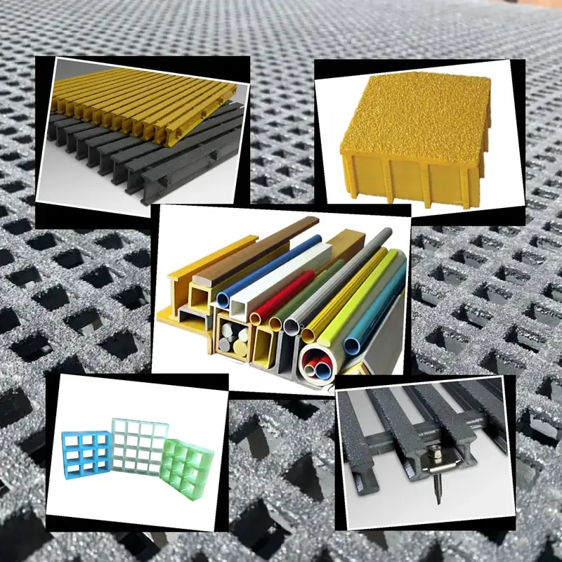
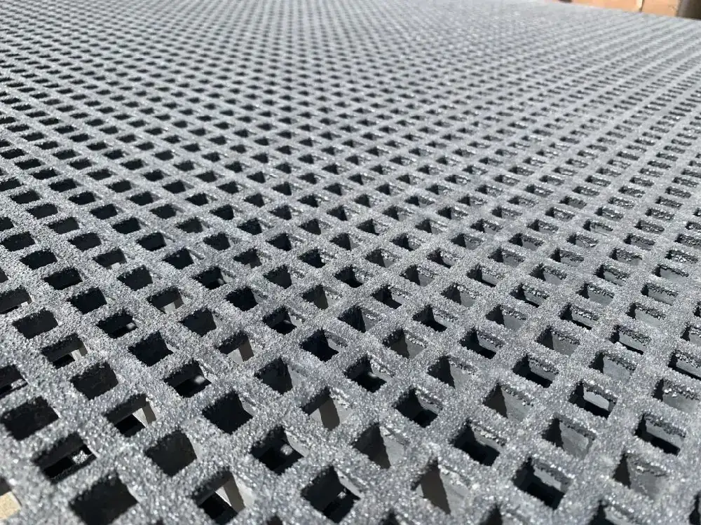
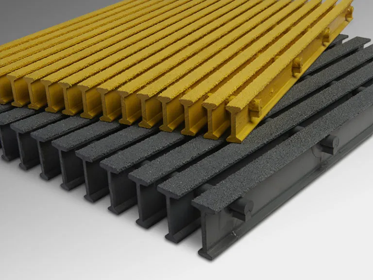
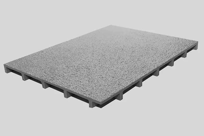
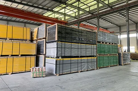
Replacing an old timber or steel pedestrian deck with FRP grating is a removal-and-refit job, not a new bridge design. The sequence is: survey the existing supports, strip the old deck in controlled sections, verify the support spacing and condition, then lay the grating to a span that stays within the deflection limit and a load case that matches the bridge's actual use. Panel joints are staggered, curbs and handrails interface to the existing structure, and a load review confirms the new deck against the old one.
- Removal: work in sections so the bridge never loses all its deck at once; keep access for inspection
- Span: size the grating to the existing support spacing at the L/200 or project deflection limit, not a generic value
- Joints: stagger panel seams so they do not line up over a single support line; seal cut edges
- Interfaces: handrail posts and curbs fix to the existing structure, not into the thin grating panel
- Supply: panel 1220×3660 mm, MOQ 10 m², lead time 12–36 working days
Why pedestrian deck replacement is a retrofit, not a new build
Most FRP grating bridge work is replacement: a timber walkway rotted, a steel deck corroded, and the owner wants a lighter, non-corrosive surface on the existing substructure. The engineer is not designing a new span; they are matching a new deck to supports that already exist and may be rusted, rotted or spaced unevenly. That constraint drives every decision.
This page covers the replacement-specific workflow: the pre-strip survey, the controlled removal sequence, sizing to the real support spacing, panel joint and stagger detail, the curb and handrail interface, and the load review that signs the deck off. It does not explain bridge structural theory.
Note: Never assume the existing substructure can carry the new deck plus its live load. The load review in section 6 is mandatory; where support condition is doubtful, the structure must be assessed before any new deck is ordered.
Survey the existing structure before stripping anything
Before the first board is lifted, record what is actually there: support spacing, support condition, curb and handrail anchor locations, drainage path, and the width and camber of the deck. Replacement decks fail most often because someone assumed the spacing and the rust didn't show until the old deck came off.
| Survey item | Why it matters | Action |
|---|---|---|
| Support spacing | Sets the grating span | Measure each bay, not average |
| Support condition | Rust or rot under old deck | Tap/inspect before loading |
| Handrail anchors | Interface fixings | Mark anchor bolt positions |
| Drainage path | Avoid ponding on grate | Note slope and outlets |
| Deck width and camber | Panel cutting and stagger | Measure at both ends |
| Live use | Crowds, bikes, carts | Sets the design load case |
Photograph the underside supports before removal. They are the reference for what the new deck bears on, and once the old deck is off, access to them changes.
Removal sequence for the old deck
Strip the old deck in controlled sections, never the whole length at once. Working bay by bay keeps the bridge walkable for inspection, lets you expose and repair supports as you go, and avoids a structure left fully open. Sequence the work so each removed bay is replaced or safely spanned before the next is opened.
| Step | Action | Rule |
|---|---|---|
| 1 | Close and barricade the section | Keep public off the open bay |
| 2 | Remove old fasteners | Note type for reference |
| 3 | Lift old deck boards | Bay by bay, not whole span |
| 4 | Expose and inspect supports | Repair rust/rot before new load |
| 5 | Measure actual bay width | Confirm against survey |
| 6 | Fit new grating to that bay | Seal cuts, clip down |
| 7 | Move to next bay | Walkway stays partly open |
Where the old deck was mechanically fixed to steel supports, check those supports for section loss before transferring the new load. A FRP deck is light, but it still must bear on sound steel or timber.
Span and deflection control on existing supports
Size the grating to the actual support spacing you measured, at the agreed deflection limit. For pedestrian bridges the common limit is L/200; where a stiffer feel is wanted, the design may call for L/360. Do not size by the old deck's thickness — size by the measured bay and the live load. The table gives factory working loads for a single simply supported span.
| Panel type | 600 mm | 900 mm | 1200 mm |
|---|---|---|---|
| Molded m25 | 12.5 kN/m² | 6.0 kN/m² | 3.2 kN/m² |
| Molded m38 | 25 kN/m² | 12 kN/m² | 6.5 kN/m² |
| Molded m38–50 | 22 kN/m² | 10 kN/m² | 5.5 kN/m² |
| Pultruded p38 | 35 kN/m² | 18 kN/m² | 9 kN/m² |
| Pultruded p50 | 48 kN/m² | 26 kN/m² | 14 kN/m² |
| Pultruded p65 | 62 kN/m² | 35 kN/m² | 20 kN/m² |
If the measured bay is wider than the chosen panel can span at L/200, add an intermediate support beam rather than over-sizing the panel — it is cheaper and stiffer. Convert with 1 kN/m² ≈ 20.9 lb/ft² when matching imperial design notes.
Panel joints, staggering and edge gaps
Panel seams should be staggered, not lined up over one support line, so a seam never becomes a long, deflecting hinge. Standard panels are 1220×3660 mm; on site they are cut to bay width and the cut edges sealed. Leave small expansion gaps at curbs and abutments, and clip panels to every support.
| Joint detail | Rule | Reason |
|---|---|---|
| Seam layout | Staggered, not in a straight line | Avoid a continuous hinge line |
| Cut edges | Seal after cutting | Stop moisture and UV ingress |
| Support bearing | Bearing on every support | No overhang past a support |
| Edge gap at curb | Small movement gap | Accommodate thermal expansion |
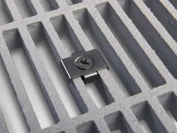
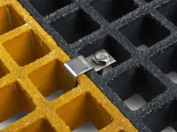
| Clip spacing | At every support | Prevent rattling and lift |
| Panel orientation | Load bars across the walk | Correct load path on supports |
Lay the load-bearing bars across the direction of travel, onto the supports. If the bars run the wrong way across a long bay, the deck will feel springy even if the panel size looks right.
Curb, toe-kick and handrail interface
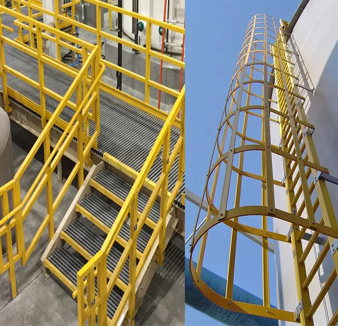
The grating panel is thin and not a structural anchor. Handrail posts, curb angles and toe-kicks must fix to the existing substructure or to a dedicated edge angle, never by bolting through the grating mesh. The panel sits between the rails; it does not hold them up.
| Interface | Fixing rule | Avoid |
|---|---|---|
| Handrail post | Bolt to existing structure | Bolting through the panel |
| Curb / toe-kick | Fix to edge angle or substructure | Relying on grating thickness |
| Deck edge trim | Clip or screw to support | Free-standing trim on grate |
| Expansion at abutment | Sliding support | Locked hard at both ends |
| Transition to shore | Flush, gritted threshold | A step that catches boots |
Where the existing handrail is reused, its anchor bolts go back into the original steel or timber. If the old curb is rotted, replace it with a corrosion-resistant angle fixed to the structure, and seat the grating against it.
Load review and acceptance of the new deck
The new deck must be signed off against a defined live load that matches real use — pedestrian crowd, bicycle, or occasional maintenance cart. The review confirms: the panel spans the measured bay within the deflection limit, the supports carry the new load, and the fixings meet the requirement. Pedestrian-surface performance follows ASTM F3059.
| Review item | Acceptance basis | Note |
|---|---|---|
| Panel span vs load | Within L/200 at design load | Per measured bay |
| Support capacity | Structure assessed | No hidden rust or rot |
| Deflection feel | No springy bounce | Walk-test after fitting |
| Surface slip | Gritted or concave | ASTM F3059 pedestrian surface |
| Clip fixings | At every support | Hand torque, no hot work |
| Edge seals | All cuts sealed | Moisture and UV protection |
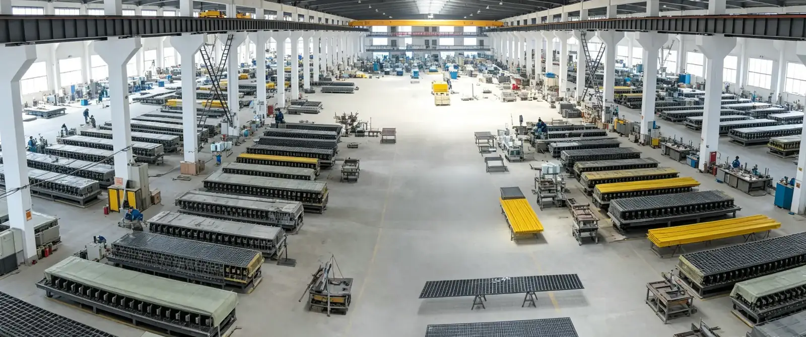
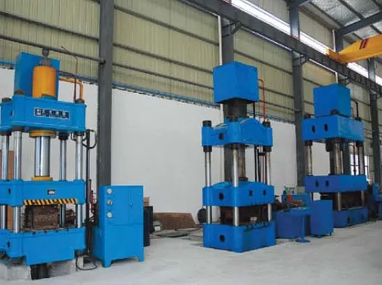
The factory holds ISO 9001:2000 (registration 01708Q11888R0S, valid 2025-03-31 to 2028-12-30), and pedestrian-surface performance follows ASTM F3059, report 211122012SHF-001, covering grating only, not profiles or handrails. Standard supply is panel 1220×3660 mm, MOQ 10 m², lead time 12–36 working days.
Panel weights and resin content for sizing
FRP's light weight is the main retrofit advantage over a corroded steel or rotted timber deck. The molded panel face weights below let you compare dead load with the old deck and confirm the substructure is not overloaded by the replacement.
| Molded panel | Face weight | Resin content |
|---|---|---|
| 25 mm | 12.5 kg/m² | 68% |
| 30 mm | 15.0 kg/m² | 66% |
| 38 mm | 19.5 kg/m² | 68% |
| 38×40 mm | 18.0 kg/m² | 70% |
| 50 mm | 27.0 kg/m² | 60% |
| 65 mm HD | 38.0 kg/m² | 56% |
Density stays 1.5–2.0 g/cm³ and delivered Barcol ≥40 under standard conditions. A light FRP deck lowers dead load versus steel, which often lets the replacement proceed on supports that would not carry a heavier new deck.
Fixings and clip choice for a bridge retrofit
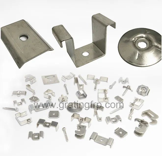
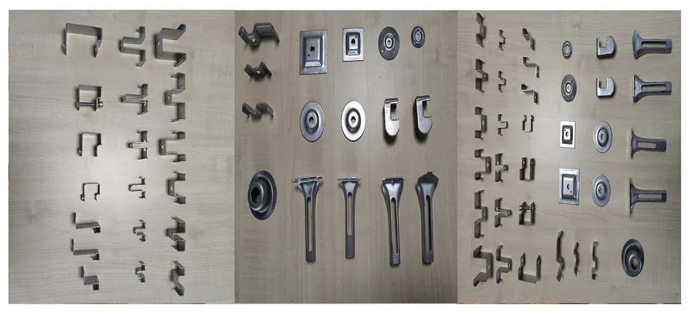
On a pedestrian bridge exposed to weather and road runoff where the bridge crosses a salted road, use SS316 clips and bolts; inland crossings can use SS304. Clip every panel to every support to prevent lift under wind or vibration, and leave one end free for thermal movement on long runs.
| Clip detail | Retrofit use | Note |
|---|---|---|
| Fixed clip | Anchors panel at supports | One end of long runs |
| Slotted clip | Allows thermal movement | Other end of long runs |
| SS316 hardware | Road salt, coastal bridges | Every exposed fastener |
| SS304 hardware | Sheltered inland crossings | Non-salt sites |
| Cut-edge seal | All field cuts | Moisture protection |
Specification checklist for a bridge deck replacement
A replacement RFQ should describe the existing structure, not just the panel thickness. The checklist below keeps the retrofit honest and matches supply to the measured bays.
| Item | State | Why |
|---|---|---|
| Measured support spacing | Per bay, not average | Sets the true span |
| Design live load | Crowd, bike, or cart | Sizes the panel |
| Deflection limit | L/200 or L/360 | Controls stiffness |
| Surface | Gritted or concave | Slip on wet bridge |
| Hardware | SS316 or SS304 by exposure | Corrosion of fixings |
| Edge seal | All field cuts sealed | Durability |
Common bridge-deck replacement mistakes
Most retrofit problems trace to assuming the structure rather than measuring it.
| Mistake | Effect | Fix |
|---|---|---|
| Assuming even spacing | Panel too long for a wide bay | Measure every bay |
| Stripping the whole deck at once | Open, unsafe structure | Remove bay by bay |
| Bolting handrail through panel | Cracked mesh, weak anchor | Fix to substructure |
| Seams in a straight line | Continuous hinge, bounce | Stagger panel joints |
| No load review | Overloaded old supports | Assess before ordering |
| Unsealed cut edges | Moisture and UV damage | Seal every field cut |
Walk the finished bridge after the first rain and after a freeze: check deflection feel, drainage over the grate, and clip tightness. A replacement deck that reads correctly on the drawing should not bounce or pond on site.
Frequently Asked Questions
Can I replace a timber pedestrian deck with FRP grating?
Yes, that is a common retrofit. Survey the existing supports, strip the old deck bay by bay, confirm support condition and spacing, then size the grating to the measured bay at the agreed deflection limit. The light FRP dead load often lets the replacement proceed on supports that would not carry a heavier new deck.
Do I need a load review before ordering the new deck?
Yes. The new deck must be checked against the actual live use — crowd, bicycle or maintenance cart — and the existing supports assessed for rust or rot. Never order on the old deck's thickness; size to the measured support spacing and the design load, signed off by the structural engineer.
How are handrails fixed to an FRP grating bridge deck?
Handrail posts, curbs and toe-kicks fix to the existing substructure or a dedicated edge angle, never by bolting through the thin grating panel. The panel sits between the rails; it is a walking surface, not a structural anchor. Reuse existing anchor bolts where the structure is sound.
What deflection limit should a pedestrian bridge deck use?
L/200 is the common starting point for FRP grating on a simply supported single span. Where a stiffer, spring-free feel is wanted, the design may call for L/360. Size from the factory load table against the measured bay and design live load, and add an intermediate beam rather than over-sizing the panel.
How should old deck removal be sequenced?
Work bay by bay, never the whole length at once: barricade the section, remove fasteners and old boards, expose and inspect the supports, measure the true bay, then fit and clip the new grating before opening the next bay. This keeps the bridge partly walkable and lets you repair supports as you go.